Introduction
An interesting example of a fatigue failure is one that was investigated recently at our Burton on Trent Laboratory. We received a call from a customer stating that they had had a failure in a shaft and requesting a visit to their site to in order that we could carry out an initial examination. The visit was duly made and a visual inspection carried out.
The failed shaft had been in service on a plate rolling machine, from new, for a period of approximately 13 months. It was reported that the machine had been operated on day shifts only and had seen duty for approximately 50% of that time. The material of manufacture was reported to have been specified as BS 970 080M40 which is a medium carbon steel. The shaft was taken to our Burton Laboratory where it was subjected to visual and metallographic examinations and compositional analysis. The results of the investigation are shown below.
Visual Examination
The examination of the fracture was carried out using the naked eye and a low powered magnifier. Examination of the shaft showed that there was no evidence of gross plastic deformation present and the general appearance of the shaft was that it was in good condition and showed no indications of having been abused.
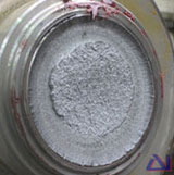
The examination of the fracture face revealed that there were a number of characteristic features that indicated the mode of failure and the general appearance showed the presence of concentric beach markings that originated from the surface of the shaft at the point where there was a sharp change in section.
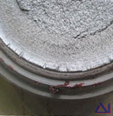
The central part of the fracture face showed different characteristics in that it was more granular in appearance and was consistent with the period of final fracture. Close examination of the outer regions of the fracture (at the circumference of the shaft) revealed that there were a number of steps associated with the origin which indicated that there had been a large number of initiation sites.
The initiation sites were located at a change in section which had a very tight radius. At higher magnifications there was evidence of quite noticeable machining marks present on the turned surface, particularly on the sharp radius at the change in section. No evidence of torsion or shear was observed to be present on the fracture face.
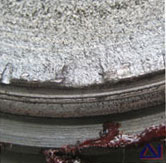
The appearance of the fracture with the stepped initiation sites around the circumference of the shaft, the tight radius at the change in section, the beach markings on the fracture face and the area of final fracture were all indicative of a fatigue crack mechanism that had operated in a rotating mode.
Metallographic Examination
A section was taken from the sample in the vicinity of the fracture in an orientation that was parallel to the longitudinal axis and transverse and radial to the fracture face. The specimen was prepared for microexamination by mounting in resin, polishing to a 1 micron finish and then etching in a solution of 2% Nitric acid in alcohol (Nital).
The microexamination of the specimen revealed that the microstructure in the shaft material consisted of grains of pearlite and ferrite in proportions that were consistent with the material specified.
The examination of the section revealed that there was no evidence of gross plastic deformation associated with the fracture, although the sharp machining marks could be clearly seen. The fracture had initiated at the tight radius at the change in section and had propagated through the structure following a transgranular path. The manner in which fracture had propagated through the structure indicated that the mode of failure had been one of fatigue. Close examination of the section in the region of the radius revealed that there was evidence of several very small secondary fatigue cracks present associated with the adjacent machining marks.
Compositional Analysis
A sample from the shaft was subjected to compositional analysis using Optical Emission Spectroscopy.
These results of the analysis showed that the material was a medium carbon steel. The results obtained showed that the elemental composition of the material was consistent with BS 970 080M40 as had been specified.
Discussion and Conclusion
From the evidence observed in the examinations and tests it was apparent that the shaft had failed as a result of a fatigue crack mechanism that had been operating in a rotating mode. The cracking had initiated at machining marks that were present on a tight radius at a change in section. The analysis of the material showed that it was correct and was as specified.
Fatigue is a mechanism of crack initiation and propagation that occurs as a result of the application of a cyclic stress. The propagation of the crack occurs in a progressive manner which generally takes place over a large number of cycles. As the crack front progresses, failure becomes more likely as the stress at the crack tip approaches the capacity of the material to sustain the load. Generally, in ferrous materials, the incidence of fatigue will only occur if the amplitude of the applied cyclic exceeds a threshold value known as the endurance limit.
If the cyclic stress remains below this value then fatigue will not occur. However, fatigue can occur in instances where the apparent stress is below the endurance limit but local stresses are higher, due to the presence of stress concentrations, e.g. machining marks, changes in section, weld defects or surface discontinuities such as plastic deformation.
The stress concentration effect in these instances is inversely proportional to the radius at the crack tip, i.e. the smaller the radius (sharper) the greater the stress concentration. In general, the smaller the radius at the section change, and the greater the difference between the two relative diameters, the greater the stress concentration factor. That factor is the number by which the calculated stress in the smaller of the two diameters must be multiplied to arrive at the actual stress present.
When fatigue does occur the initial phase tends not show any evidence of cracking. It is only when the component has reached approximately 85% of its ultimate fatigue life that the first indications of fatigue crack growth will be observed. The final part of the fatigue life from first cracks to failure therefore generally occurs in the last 15% of the total component life.